Stray Voltage from Stray Current,
and viceversa
Stray Current and Stray Voltage are normal side effects of electrical systems as built and as interconnected. The interconnectedness is a necessity to mask a failure mode from the time of Edison, that causes fires (in North American systems). Thes side effects provide avenues of irritation or shock that should not exist, but do. It is both a Utility and User owned and produced ailment. So blindly pointing the finger at "them" may make you look like a fool, should you become informed that the major contribution is yours. Herein then, is the basis for why it occurs, from a basic construct to the contemporary electrical setting.
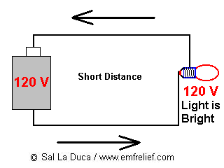
When a source of power is connected to a load, a current flows producing some effect: heating, ventilation, lighting, etc. When the source and the load are close by, the situation is shown below.
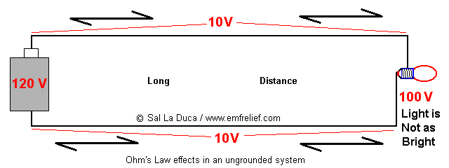
When the source and load are a long distance apart (perhaps a few miles), the very low resistance of the wire becomes significant. That is because the wire resistance will cause a resistive voltage to be developed over the length of the wire that will substantially reduce the voltage available to the load (and of course, with more current, the greater the resistive voltage loss), as shown below. That is one of the reasons we do not have a DC power distribution system.
With Alternating Current (AC) systems the wire resistance problem can be compensated for by using high voltages (with a corresponding lower current for the same power, and a simultaneous reduction in the resistive voltage produced over the long wire distance) and stepping down to the required voltage through a transformer, at the point of use. So if the power is sent at 4800 volts, even a 100-volt reduction will seem small when the voltage is stepped down to 120/240, keeping it within reasonable and expected limits. Transformers, and their ease of changing one voltage to another is a second reason we do not have a DC power distribution system. The example shown below is particular to the Delta (ungrounded Primary) distribution system.
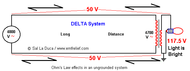
The basic (and simplified) relationship is Power = Voltage x Current. So in a perfect world you can raise the voltage, lower the current, and have the same power. Current develops the voltage differential from the source to the load by the relationship Voltage = Current x Resistance, so it logically follows that for long-distance power cartage with minimal losses, the lower the current, and of course the higher the voltage, the better. Since we are a power-hungry community, it is not uncommon to have power lines criss-crossing the countryside at 35,000 to 750,000 Volts, just to minimize that current.
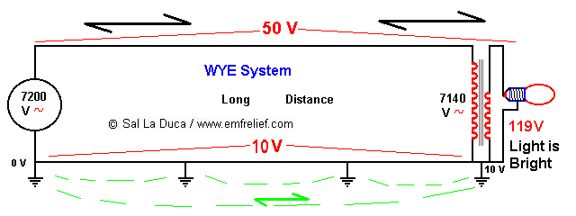
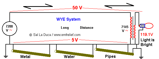
Another distribution system (WYE, as shown below) employs a wire as a "ground" reference. It is connected to the earth at many points along the path of travel from source to load. Although in the previous examples it was simply shown that an ientical voltage was developed along each leg of the circuit, reducing that available from the source, in a WYE system a counter-intuitive process occurs. That is, at the source one leg of the circuit is connected to ground and is theoretically at zero volts, so that at a distance a voltage is produced on the grounded wire that adds to zero, producing a voltage increase above zero, while the energized leg develops a voltage drop that decreases the available source voltage. The concept is the same as in the other examples, except that now there is a local ground reference voltage to deal with. In this type of system, although the wire resistance comes into play in a still limited fashion (because of the reduced currents due to the use of high voltage), it is not uncommon to find the "ground" reference to be at 5-15 volts different than the earth. Although the earth is a generally poor electrical conductor, some current will still flow through it. Additionally, since the earth is a unified mass (although from a Local perspective it is Not homogeneous), it\\\'s at the same electric potential (not unlike the ocean being overall salty) from a power system perspective, and so exerts a restrictive force on the buildup of voltage on the grounded wire.*
In the diagram below, the complexity increases significantly because of the redundant current paths on the return/neutral/ground wire due to the interconnection to public water main systems (while some may think that current will flow through "the" path of least resistance, in fact current will flow through all available paths, with the amount of flow affected by the individual path\\\'s electrical resistance). This serves to reduce the overall voltage drop produced in that leg of the circuit. However, the voltage may still be high enough to produce a shock in creatures in electrical contact with the earth (GPR). This is sometimes called a "tingle voltage." A break in any one of the redundant neutral paths will produce an increase in "ground" voltage from source to load (due to an increase in the overall equivalent resistance), and a corresponding elevation of the voltage at the ground rod at the point of use, even though the rod is stuck 8-10 feet into the soil! A break in the primary return wire can now also cause unrestricted primary current flowing through the redundant paths provided, which may also include CATV, Telephone, etc.
Thus far, the above contributions are related to the utility alone. The customer\\\'s contributions are outlined below.
A common North American residential wiring system is comprised of three wires providing two 120 V sources and one at 240 V, as shown below. They connect to a transformer as shown in the sketch following.
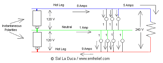
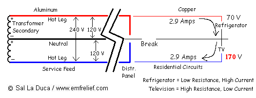
However, as with all mechanical systems, it requires maintenance. But that is not what the typical homeowner is equipped for, because that is not the promoted perception. So connections become frayed and loose due to oxidation over many years, especially due to the use of Aluminum wire (primarily used by the electric utilities as a necessity of economics). When the middle-wire (return/neutral/ground) connection becomes loose, it can present voltages within a single residence that are a fire hazard, as shown below. While 240 V devices continue functioning properly, 120 V devices now have unstable voltages, and those experiencing the higher voltages may ignite spontaneously, even simply when a light switch is operated, causing an instantaneous imbalance. Cool, huh? This is know as a "Bright and Dim lights" situation, in electrical parlance.
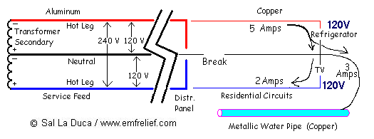
The solutions to this dilemma were to either educate the consumer, or mandate how things were to be wired in the future (the path of least resistance). As this latter path was chosen, metallic water piping came into play to provide a voltage stability solution, by providing an alternate path for return current flow, that really belonged on the middle wire (return/neutral/ground), as shown below.
So the interconnection now commonplace, even new installation will experience split currents flowing where they should not.
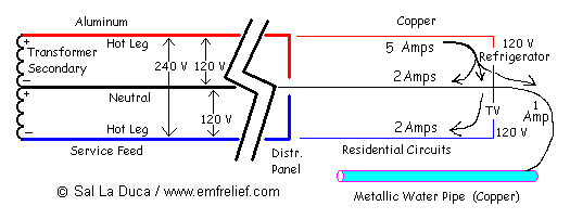
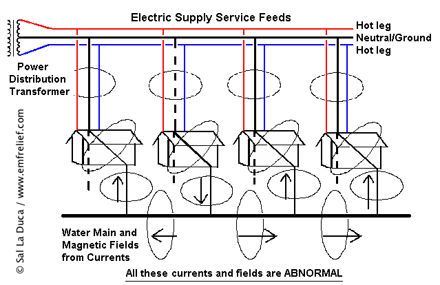
When that neutral current flows through metallic water piping it becomes an electrocution hazard to the weekend plumber, and a source of stray current that is shared by several or many neighbors, depending on the integrity and construction of the distribution system, as shown below.
In addition to the common problem above, even if everything is wired properly, there may be occasion to find elevated voltage levels at the residential grounding point (relative to earth ground) due to currents on the neutral wire. These customer low voltage currents, being perhaps 50 times greater than primary currents, will develop a voltage across the run of wire from the distribution panel and grounding point to the source transformer, as shown below. Again, in such instances a dog, cow, or a barefoot human in electrical contact with the earth will be shocked when it touches anything connected to the electrical system "ground" such as a water spigot, a ground rod, etc.
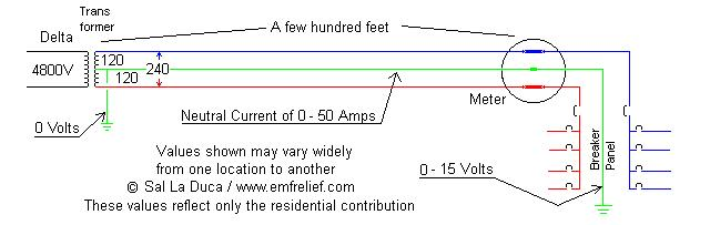
The neutral current can be reduced by statically balancing the loads (attaching circuits to different sources) such that most of the current travels on the energized wires, with cancellation occurring within the common neutral. However, it can never be totally eliminated because it\\\'s not possible to predict what will be energized when, so dynamic balancing is a myth.
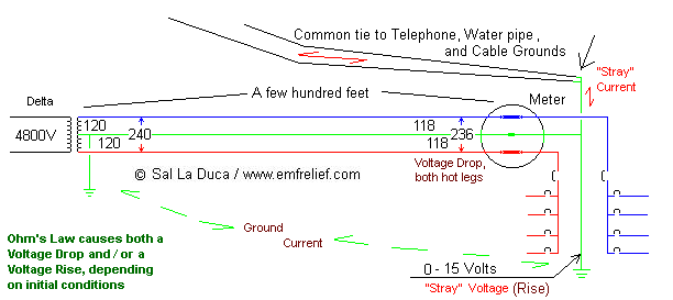
Some related problems, because of the requirement to interconnect Cable and telephone grounds to the electrical system ground, ensue because of duplicate paths for the return (neutral) current to flow, as shown below. Even a few volts of difference between the earth ground and the electrical system ground is sufficient to drive significant currents through the Cable shield causing TV interference, and through the telephone ground causing an AC voltage presence on the associated internal wiring.
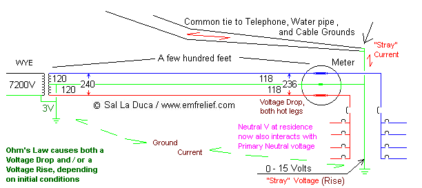
This gets even more convoluted when the Primary system is WYE, because now there is voltage on the primary neutral, which will either add to or subtracts from (based on the polarity of the source voltage in use), the neutral voltage developed at the residence, as below.
One way to identify the presence of stray voltage (caused by stray current) is with a cheap Gaussmeter ($45+/-), as any uncanceled current path (net current / stray current) will exhibit a magnetic field with a large physical footprint. This picture get muddled, however, when common indoor wiring errors occur, causing a magnetic field presence that can engulf the entire residence. Another is by using an AC voltmeter that can read down to 50 milliVolts and has a 10 Mega-ohm input impedance to measure stray voltage. Cheaper meters have a lower input impedance and significantly reduce the ability to detect small voltages.
While "experts" and "authorities" have tried to define a voltage level above which action should be taken (and some "authorities" have suggested 1 V), that level may still be too high for certain individuals or animals. The relevance can vary based on the age and health of the affected individual or animal, among other things. As in all irritants, the end goal is to try to reduce levels to As Low As Reasonably Achievable (ALARA), with strong emphasis on Reasonable. "Reasonable," however, is defined differently by different parties, partly based on who understands the origin of the problem, but primarily based on how much money and effort are required to reach ALARA, and who\\\'s going to absorb the cost, which is where the finger-pointing and litigation occur. Nevertheless, below are practical steps to approach that ALARA.
Some of the possible recourses for Residential-Generated "Stray Voltage" are:
1) Increase the neutral wire size to the source transformer (to reduce neutral wire resistance),
2) Provide a better balancing of loads between energized buses (to reduce neutral current),
3) Reduce the number of sources fed from 120V, and increase those fed from 240V (to reduce neutral current),
4) Bring the source transformer closer to the point of use (to reduce neutral wire resistance),
5) Periodically inspect all connections for snugness and integrity (especially the neutral) at least every 10 years,
6) Eliminate the use of the interconnected metallic water piping as a "shared" grounding point, yet retain local grounding for lightning protection.
While these may appear simplistic, there are specific additional details that need to be observed for each alternative, to ensure a safe application.
Some of the possible recourses for Utility-Generated "Stray Voltage" are:
1) Increase the size of the primary neutral wire (to reduce neutral wire resistance),
2) Provide a better balancing of loads between phases (to reduce neutral current),
3) Provide regular changes between WYE and DELTA feeds to customers along a circuit (to eliminate long spans of redundant current paths),
4) Provide non-conductive breaks in the public water main at regular intervals.
5) Periodically inspect all connections for signs of deterioration (especially the neutral), using infrared photography under heavy load conditions. Repair as necessary,
6) Perform regular magnetic field surveys to identify problems before they become troublesome,
7) When the voltage difference between the electrical system ground and any other point in the soil (say as little as 10 feet away) is excessive, request neutral isolation from the local utility.
Again, while these may appear simplistic, there are specific additional details that need to be observed for each alternative, to ensure a safe application.
You be the judge as to what is excessive. I see that voltage difference to earth regularly around 1/2 Volt (500 mV), but have seen it as high as 25 Volts. Sensitive people (children, the elderly, the sick, etc.) can sense very low values (perhaps even less than 100 mV) and be irritated by it.
Values shown herein are for illustrative purposes only, and do not necessarily reflect all variants of real-life application. Additionally, primary systems are comprised of 3 phases, whereas only one phase is shown within this document. This brief is not meant to be exhaustive or all-inclusive, and real-life remedies are bound to comprise components of each category.
Disclaimer: Electrical systems are by their very nature dangerous and, if certain precautions are not followed when testing, maybe even fatal. Please, please, if you have any uncertainty in what you wish to do, hire someone that is competent. If there is any question of unfamiliarity by someone who is supposed to be "competent", print this page and have them read and understand it before proceeding. Nonetheless, I cannot be held liable for failure to follow proper technical precautions.